Restoring a Roland MT-120: Building an Arduino Floppy Drive Tester
An old Roland MT-120 was the starting point for an unexpectedly interesting embedded project. I wanted to restore the instrument, but its floppy drive was not working correctly. Before replacing parts or making mechanical adjustments, I needed a way to control the drive independently and see what its signals were doing.
That led to FDTester: an open-source Arduino-based tester for standard PC-style 3.5-inch floppy drives. Rather than attempting to read files, it exercises the drive's mechanical and electrical interface directly.
Scope: FDTester is a mechanical and electrical diagnostic tool, not a complete floppy disk controller. It does not decode MFM sectors, read filesystem data, or prove that the magnetic read channel works.
The problem: a drive that could not read other disks
The Roland MT-120 restoration raised a practical question: was the failure caused by the drive mechanics, its interface signals, the spindle speed, or head positioning? In particular, Track 0 alignment was a challenge: the drive did not reliably read disks written by other devices.
A drive can respond to motor and seek commands while still being unable to read a disk correctly. A Track 0 sensor confirms that the mechanism reached its reference position; it does not, by itself, prove correct radial head alignment or interchangeability with another drive. That distinction shaped the test strategy.
Architecture: separating control from the host
FDTester uses an Arduino as a small, dedicated interface controller. A serial terminal sends commands; the Arduino drives the floppy interface and reports status and measurements. The repository documents an Arduino Uno / ATmega328P reference setup, while its project description also mentions Mega compatibility.
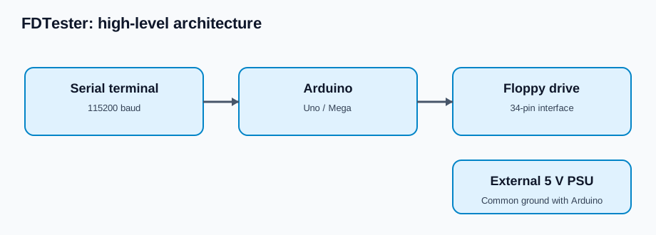
The repository's validated target is an Epson SMD-300, configured for DS0. This is the documented test configuration; compatibility with other drives depends on their pinout, jumpers, and electrical characteristics.
The floppy drive has its own external 5 V supply (the README specifies approximately 1 A capability), with a common ground shared with the Arduino. Do not power the motor from the Arduino USB port. A ULN2803 or appropriate transistor buffering is recommended for the active-low interface lines; check your exact drive's electrical requirements before connecting it.
The signals that matter
A classic 34-pin floppy interface gives direct access to the most useful diagnostic controls and feedback signals:
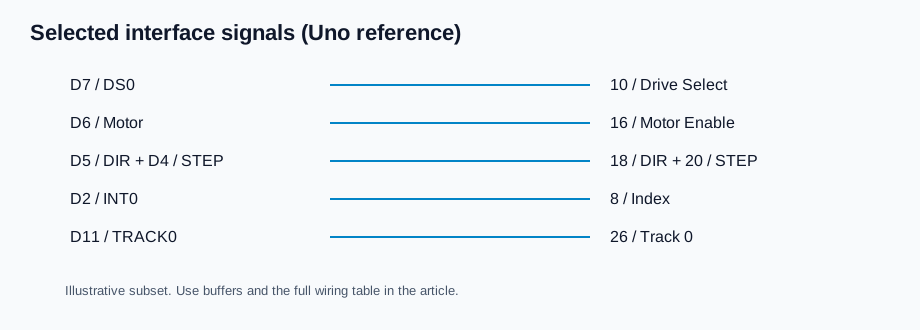
| Floppy pin | Signal | Arduino Uno pin | Diagnostic purpose |
|---|---|---|---|
| 10 | Drive Select 0 | D7 | Select the target drive |
| 16 | Motor Enable | D6 | Start and stop spindle |
| 18 | Direction | D5 | Set seek direction |
| 20 | Step | D4 | Advance the head by one track |
| 32 | Side Select | D8 | Select head 0 or 1 |
| 8 | Index | D2 / INT0 | Count revolutions |
| 26 | Track 0 | D11 | Detect home position |
| 28 | Write Protect | D12 | Inspect disk protection status |
| 34 | Disk Change | D10 | Detect media change (default configuration) |
| 24 | Write Gate | D9 | Dangerous write control; locked by default |
Important: The table reflects the repository's Epson SMD-300 / DS0 wiring. Odd-numbered connector pins are grounds. Pin 34 may have a different function on other drives or jumper settings. Pin 2 (Density Select) is left unconnected in the documented setup.
Diagnostic workflow
I wanted a repeatable way to distinguish an interface problem from a mechanical problem before attempting fine adjustment.
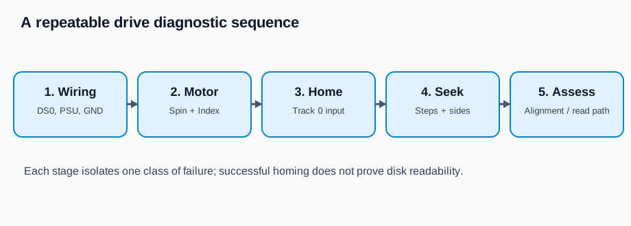
The basic sequence is straightforward:
- Check wiring and drive selection. Confirm common ground, the external supply, and the DS0 jumper configuration.
- Spin the motor. Confirm that the mechanism starts reliably.
- Measure rotational speed. Count Index pulses over a known interval.
- Home the head. Move toward Track 0 and inspect the Track 0 signal.
- Exercise stepping. Seek to known tracks and sweep across a range to reveal mechanical issues.
- Inspect status lines. Check Write Protect and Disk Change while inserting or removing media.
- Evaluate disk interchangeability separately. If disks from other devices still cannot be read, investigate mechanical alignment and the read path using appropriate reference media and equipment.
RPM measurement using the Index pulse
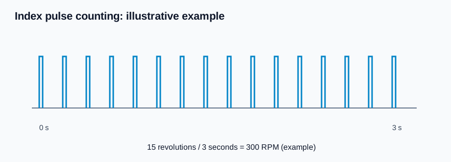
The Index signal provides one pulse per revolution on a typical drive. If N pulses arrive during a measurement window of T seconds, rotational speed is approximately:
RPM = 60 × N / T
For example, 15 pulses over three seconds corresponds to about 300 RPM. That is a calculation example, not a recorded measurement from the Roland restoration.
Track 0: homing is not alignment
The most interesting part of this repair was Track 0. Homing tells the firmware where the mechanism's reference sensor is triggered. However, an incorrectly positioned head assembly can still produce a plausible Track 0 signal and fail to read disks recorded by another machine.
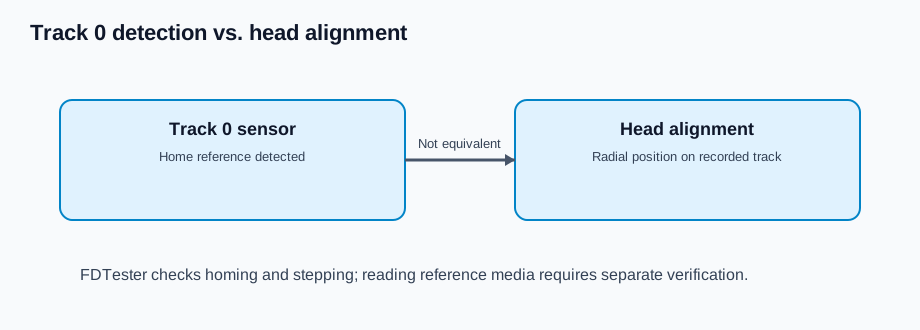
This is why I treated Track 0 detection and head alignment as different problems. FDTester can help with the former and with repeatable movement tests; it cannot directly measure magnetic head alignment or validate sector decoding. Alignment should be checked against appropriate reference media or specialist equipment rather than inferred solely from the Track 0 switch.
Using FDTester
The firmware exposes a simple 115200-baud serial console. Once the drive is wired and powered correctly, these are useful commands from the published README:
P                  # Report status
M                  # Toggle motor
R 3                # Measure RPM for 3 seconds
H                  # Home to Track 0
G 40               # Seek to absolute track 40
S 1                # Select side 1
T 0 79 100         # Sweep tracks 0–79, 100 ms dwell
RATE 6             # Set stepping interval to 6 ms
?                  # Show help
The firmware also includes Write Gate controls protected by an explicit UNLOCK command. Do not unlock or assert Write Gate on a disk containing valuable data. None of the diagnostic steps above requires writing to the disk.
See the source sketch and README for the implementation and full command reference.
What the tester can—and cannot—tell you
FDTester is useful for isolating failures in spindle control, stepping, drive selection, home sensing, status wiring, and basic timing. It also gives you a repeatable way to move the mechanism while inspecting its behavior.
It does not establish that the read head, analog read channel, MFM decoding, or media are good. If the drive responds correctly to all commands but cannot read disks from other devices, the next step is targeted read-path and alignment diagnosis, not an assumption that the controller has fixed the problem.
Lessons learned
The most valuable outcome was not a new storage controller; it was observability. Breaking the drive into independent signals and commands turned a vague "doesn't read disks" failure into a sequence of testable questions.
For me, the Roland MT-120 restoration was also a reminder of why embedded engineering is rewarding: software, timing, electrical interfaces, and mechanics all meet at the same debugging bench.
Related projects
- From BlueSCSI Ultra to DaynaPORT: the same kind of hands-on work on legacy SCSI devices, from the controller side.
- Recovering Iomega Media in 2026: the floppy-era hardware story continues with Jaz and Zip drives and QIC-122 tape.
Project: FDTester on GitHub · Arduino sketch · GPL-3.0 license
Diagrams in this article are conceptual illustrations, not oscilloscope captures or a certified wiring schematic. Confirm connections against the repository and your drive's technical manual.